How to assemble the measuring instrument
This section explains how to assemble the measuring instrument. You will need to bring the different elements together before assembling them. Here is the list:
- A waterproof housing, which will contains the other elements;
- A MLX90614 infrared thermometer module, the main sensor;
- An Arduino-like Nano board, which will controls the sensor;
- A terminal adapter to fix the Arduino board into the casing and facilitate maintenance;
- A little fan for Raspberry Pi to force ventilating the housing;
- A long mini-USB to USB cable to communicate with a computer;
- Some screws, nuts and jumper wires.
Note
Linked references are from the AliExpress marketplace; obviously, it is certainly possible to obtain equivalent material wherever you want.
You will also need for many tools such as screwdrivers, column drill, drill bits of various sizes, hole saw, chamfering cutter, cutter, soldering iron, solder, etc.
Step 1: drill holes in the casing
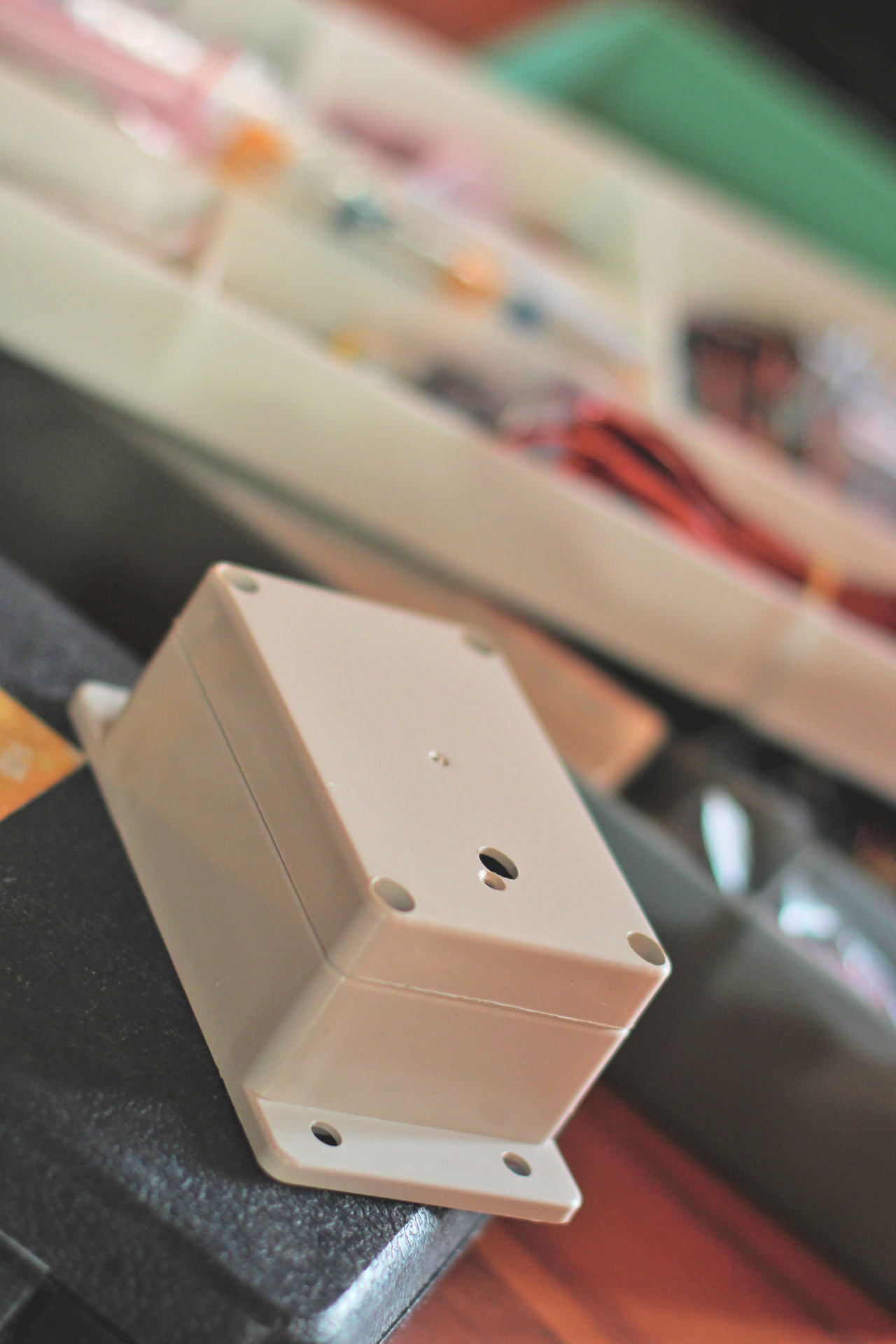
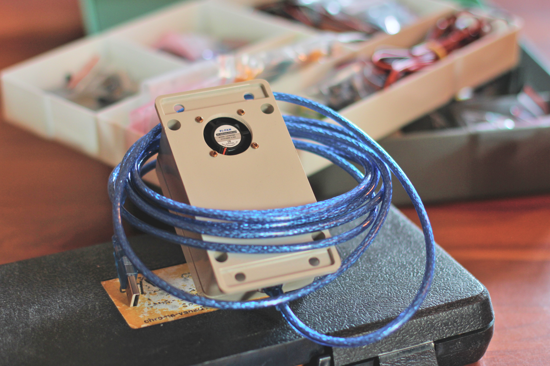
The fan will be installed at the back side of the casing to prevent rain to enter. Its main role is to prevent temperature rise inside for a more accurate measurement. Near a border, drill a big hole for ventilating, and four holes for fastening screws.
Back side of the casing
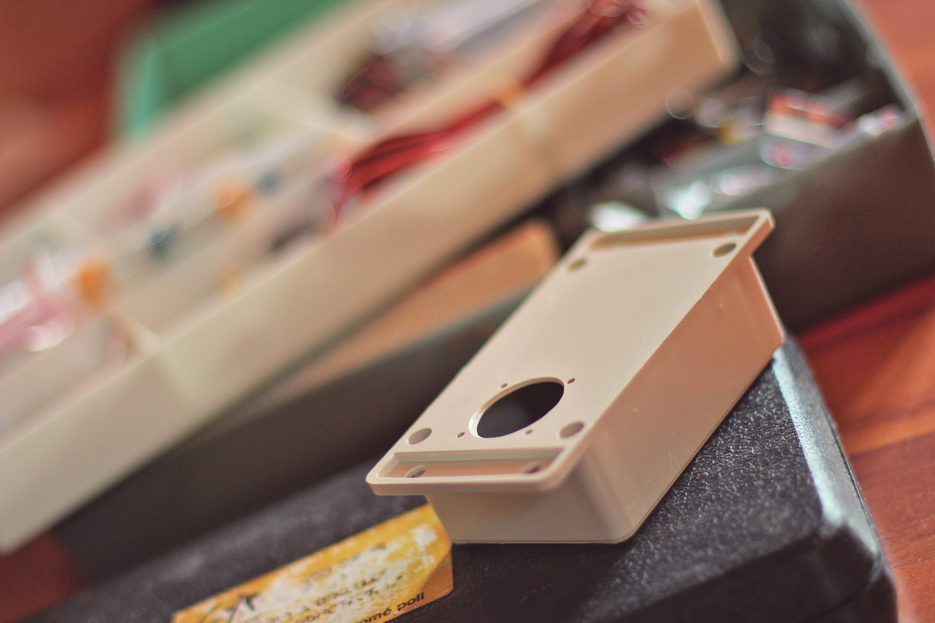
The infrared module will be watching for the sky. Drill a hole on the front cover for it, facing the back side fan hole. Drill a second chamfered hole nearby, for a fastening screw.
Front cover of the casing
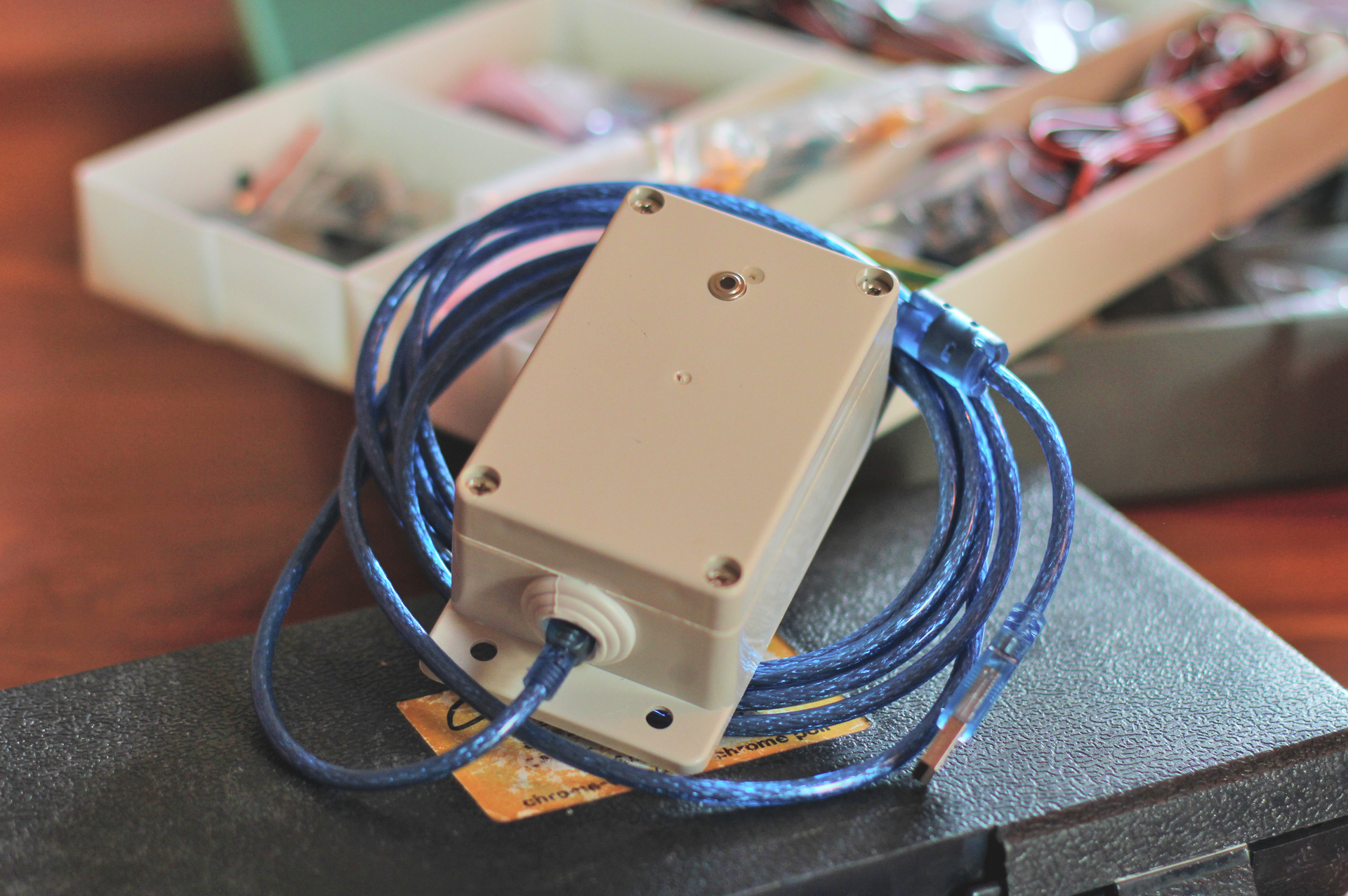
The USB cable will be plugged by the bottom side of the casing. Drill a big hole for hit, protected by a recycled rubber grommet.
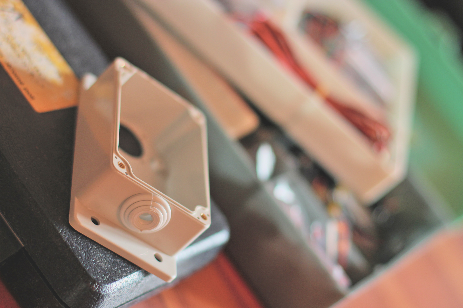
Bottom side of the casing
Step 2: prepare the components
The Arduino board and the infrared module are shipped with male pin headers to be soldered. The waterproof housing is shipped with a gasket to be correctly installed in the groove of the casing cover designed for this purpose.
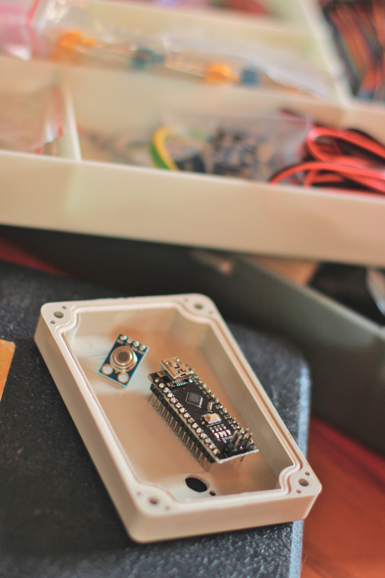
Electronical components
It could be more difficult to clamp wires on the terminal adapter once it is fixed. So it could be a good idea to screw jumper wires on good blocks for infrared sensor and fan just before.
Infrared sensor wires must be clamped in 3.3V, GND, SDA (A4) and SCL (A5) terminals. Fan wires must be just clamped in 5V and GND ones.
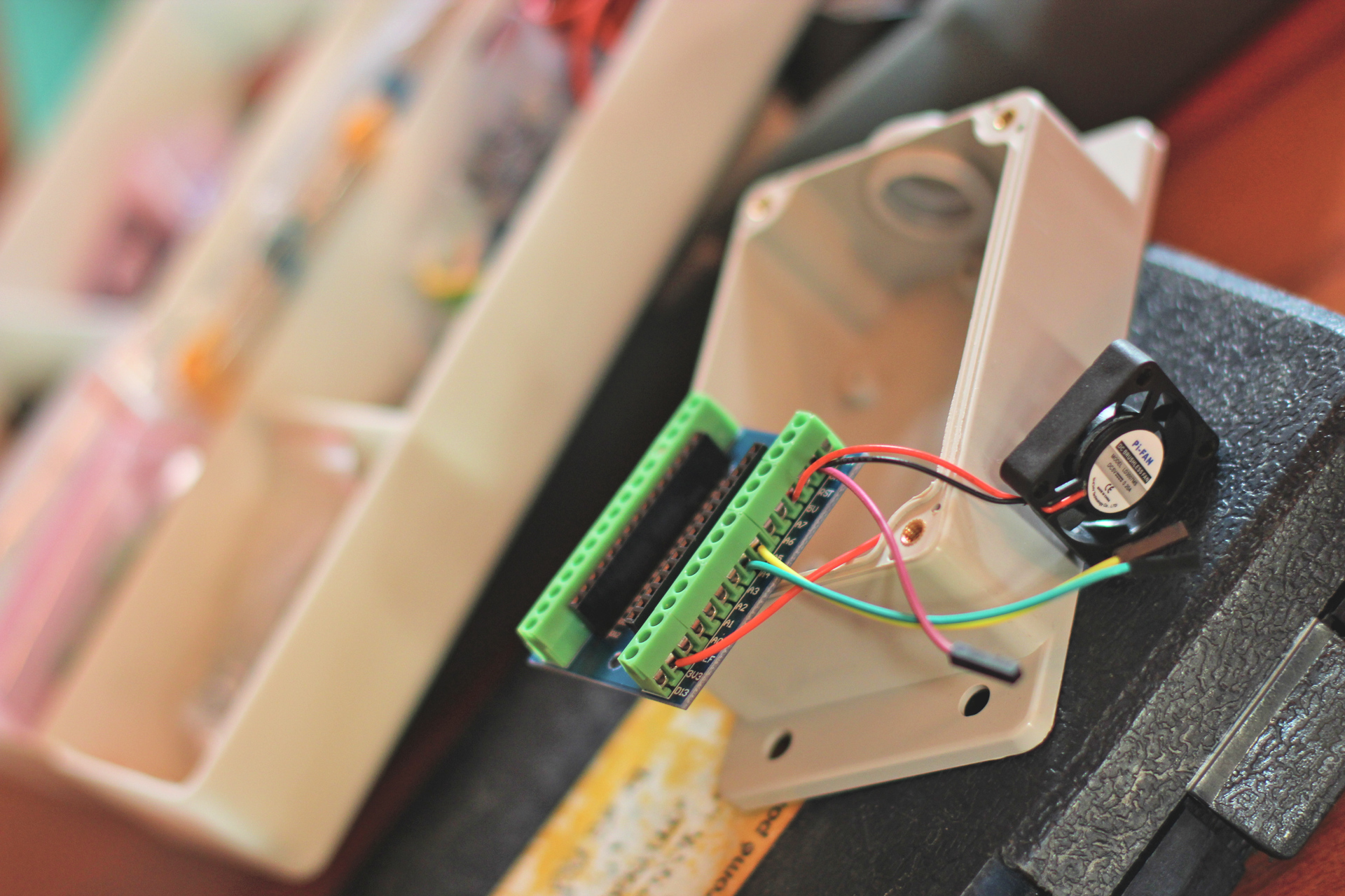
Assembly terminal adapter
Step 3: assemble the elements
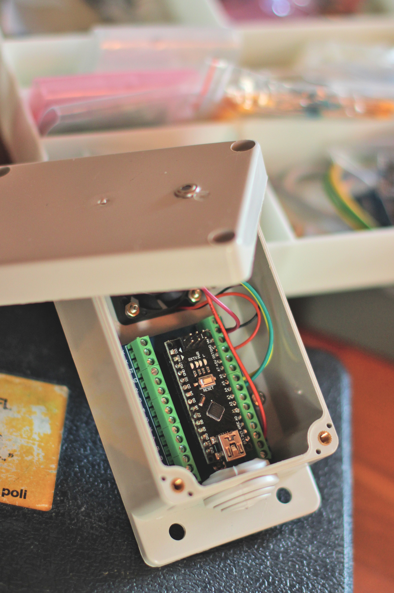
Everything is ready! The terminal adapter can be screwed in the casing, along with the fan.
Note that three screws are threaded into the plastic studs of the housing. Only one through the terminal adapter, two others squeezing it on both sides.

Fix terminal adapter and fan
Next, screw the infrared sensor on the front cover, with a bit of silicone for sealing. One screw is enough. Plug jumper wires on sensor, and insert the Arduino board on the adapter.
Ending assembly
Once done, you can close the housing, plug the USB cable and admire the splendor of your work with your proud wet eyes!
Back side of the instrument
Front side of the instrument